During this mission, a series of technological tests were carried out to qualify concepts or systems under development, which will eventually be used under operational conditions in scientific projects and campaigns.
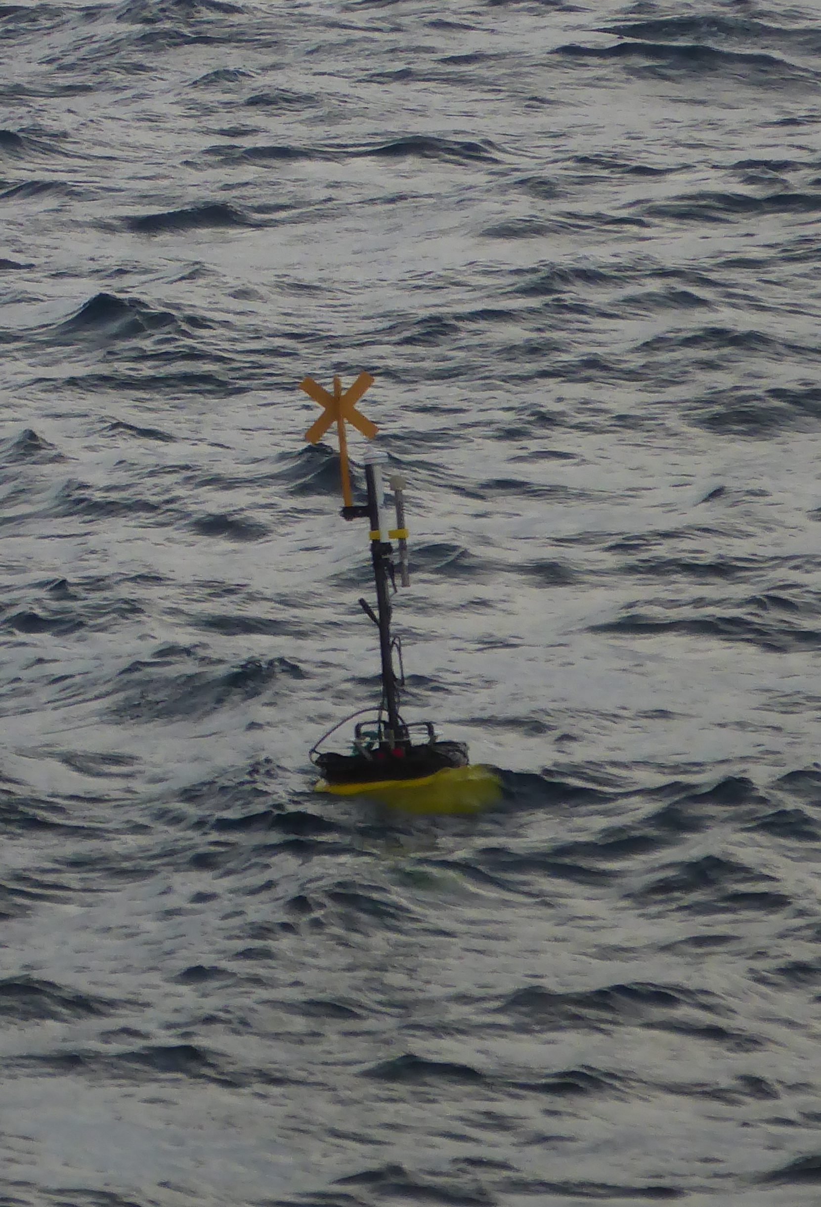
MicroRiyo tests: The term MicroRiyo used in this document refers to the use of a microstructure measurement instrument (microrider) that moves in yo-yo mode (up/down) along a wetting line. The microrider is an instrument designed to measure velocity shear and temperature variability on vertical scales of less than one millimetre.
Tests on the COGNAC float prototype: The Cognac float is a low-cost acoustic float developed jointly by teams from LOPS, ENSTA Bretagne, the RDT (Technological Research and Development) department and Ifremer's NSE/ASTI (Underwater Acoustics and Information Processing Department).
Qualification of the Deep Argo 'Tri-head' float: The qualification of this ARVOR float, equipped with several CTD sensors, will make it possible to compare the different CTDs and ultimately define the sensor that could be installed on future ARGO floats.
MicroRiyo tests: the ultimate goal is to have a system for observing the oceanic microstructure on a mooring, capable of studying the dissipation of kinetic energy and the intensity of mixing by carrying out repeated vertical profiles autonomously.
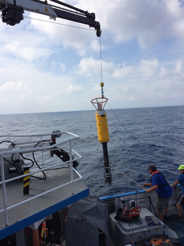
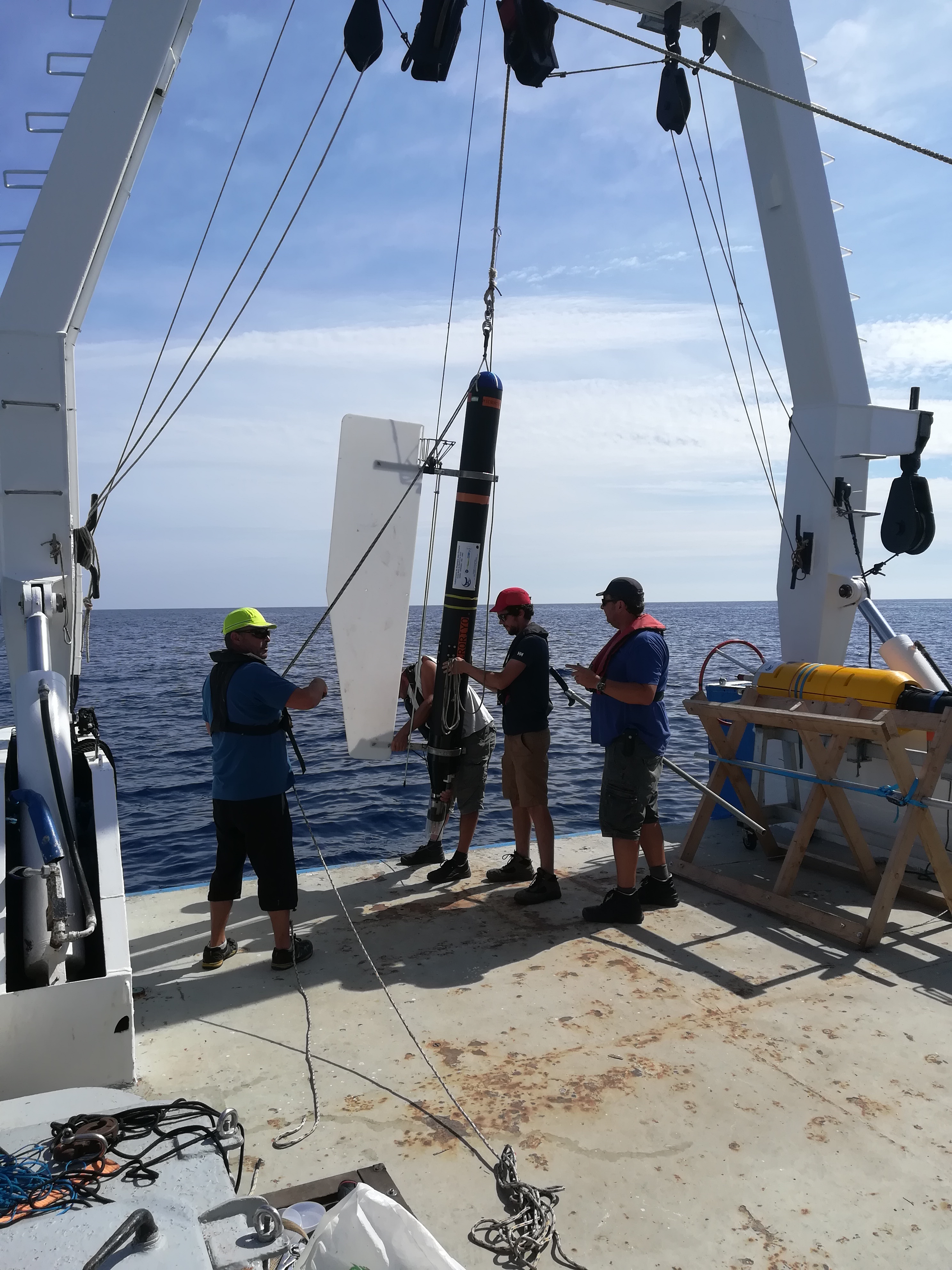
The aim of these tests was to test version 2 of the vehicle and to identify a number of critical points with a view to moving the project forward. These tests follow on from the ESSLOPS campaign (2017), which used version 1 of the vehicle and whose preliminary results were encouraging. The vehicle has been modified into a version 2, the main differences of which are
- the use of a MicroRider (MR)-6000, which replaced the MR-1000 borrowed in 2017 from our Norwegian colleagues at UIB (Bergen). The MR-6000 weighs almost 6 kg in the water, compared to 0 kg for the MR-1000. The choice of an MR-6000 (purchased by LOPS at the end of 2017) was necessary to deploy the mooring on deep bathymetric structures to study current-topography interactions.
- Removing the external buoyancy that surrounded the top of the vehicle on version 1 to reduce the drag of the vehicle as it moved along the line. Reducing drag is a never-ending quest, as it affects vibrations, the speed at which the instrument falls and rises, the ballast required to achieve a given fall speed, etc.
- Replacement of the rings through which the mooring line slides: use of Teflon rings instead of stainless steel rings.
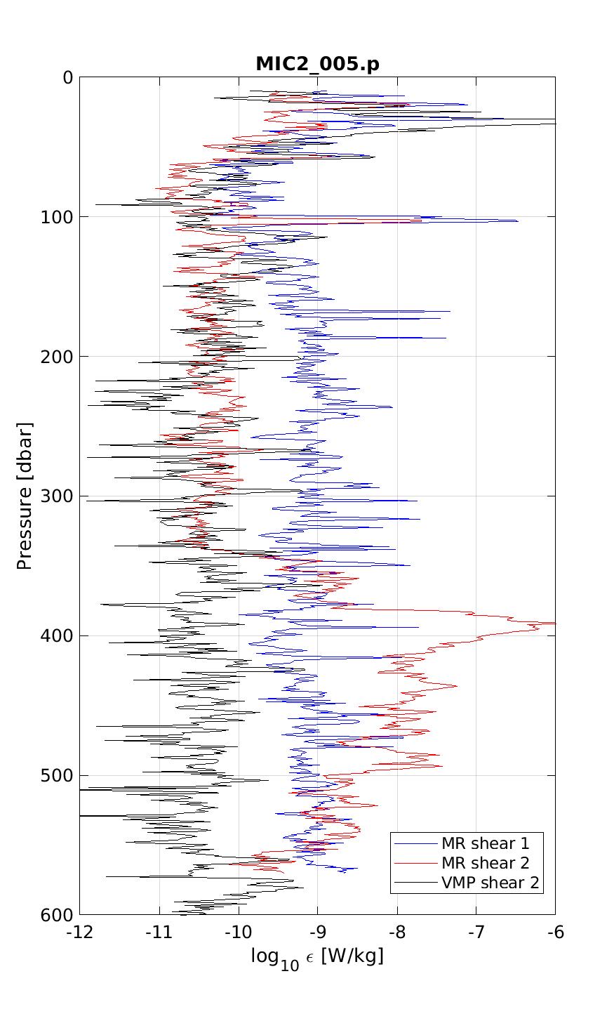
Profiling with a VMP6000 was carried out in parallel with the MicroRiyo measurements. Several tests were performed:
1/ To compare the intrinsic noise level of the vector with the VMP6000 when the MicroRiYo vehicle is in near free fall without the constraint of the mooring line.
2/ To validate the ability to cycle (ascend and descend) along a Dyneema cable of a MicroRider installed in a buoyant HDPE tube.
3/ To validate the ballast recovery system.
The sea trials revealed that
- demonstrate an intermittent fault in the MR-6000 inclinometers, which subsequently necessitated the replacement of one of the electronic cards under warranty.
- o show that one of the two channels (#1) measuring velocity shear almost systematically gives a stronger signal than the other channel (#2) (as well as in comparison with the VMP measurements) when the vehicle is forced to move along the line (a problem that does not exist when it is in quasi-free fall). This overestimation of the signal is independent of the number of sensors used.
- To show that the trace (#2), which compares very favourably with the VMP measurements in the underground, suddenly becomes bad at a given moment below 200 m.
- Adjust the ballast recovery system located in the lower part of the mooring line. Initial tests showed that if the distance between the ballast release point and the recovery net was too great, the ballast could not be recovered effectively.
Tests on the COGNAC float prototype: The aim was to generate data to test the acoustic system (RTsys SDA14 source and electronics and loggerhead hydrophone) of a low-cost float and to test the sensitivity of the geolocation quality in different configurations: depth of the sources, distance between source and float. These initial tests were also an opportunity to test various aspects of the float (dynamic behaviour, buoyancy, energy autonomy, transmission capacity, etc.).
The COGNAC tests allowed :
- To highlight the lack of autonomy, especially during the servo phases of the float control system, compared to the specifications.
- Define the specifications of the new acquisition and regulation system based on a Teensy card (without on-board OS), in particular to significantly increase the autonomy of the float.
- To validate the acoustic acquisition system that currently equips the floats and to get to grips with the RtSys acoustic source.
- To obtain a first set of acoustic data to validate the RtSys source system, the electronics of the acoustic receiver system and the hydrophone currently fitted to the floats.
In general, these tests allowed the current version of the float to be fine-tuned in terms of mechanics, electronics and software.
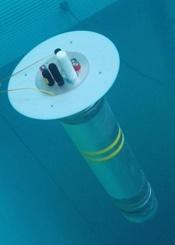
Figure 2: Cognac float (2022 version).
Qualification of the Deep Argo 'Tri-head' float:
These tests, carried out with our colleagues from Ifremer's RDT (Research and Technological Development) department, enabled us to carry out the first stage of qualification (end of qualification tests successfully completed in May 2019) of a platform that allows us to make very good in situ comparisons of different CTD sensors, to check their dependence on pressure, their accuracy and their long-term stability.
These deployments lasted only a few days and were limited to a depth of 2000 m. They confirmed all the functional aspects and the acquisition performance of the instrument, but did not provide enough in situ data to draw any conclusions about the performance of the sensors.
Since then, a long-term deployment of these floats has been carried out during the RAPROCAN2020 campaign.
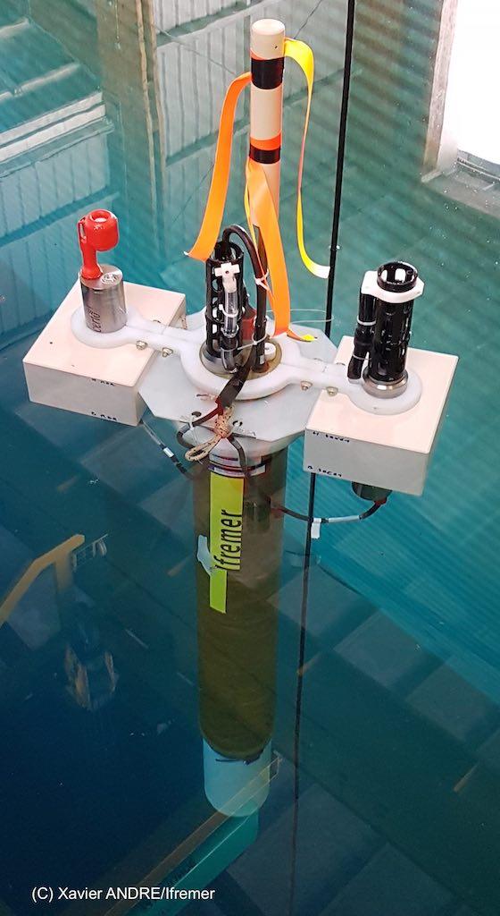
Figure 3: 'Tri-head' float
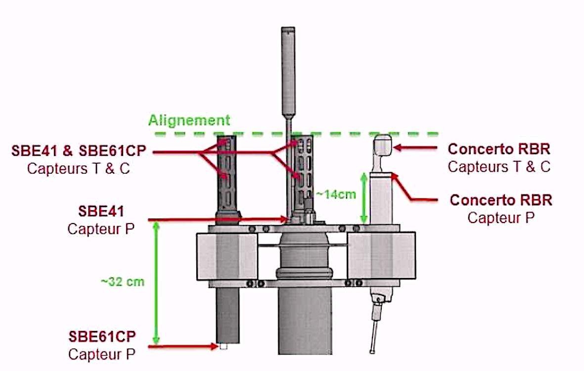
Figure 4: Location of the different types of sensors